| [E-mail] | |||
Freshwater aquariums can develop at their water-air interface an oily, whitish, sometimes bubbly film. This film is the result of interaction of molecules of proteins and other organic by-products from fish food and waste with the surface tension of the water. In tanks used mostly for fish keeping this is not usually a problem though. The strong surface agitation and current provided by air stones and powerheads is normally sufficient to break up the film and keep the molecules from binding to each other and to the surface until they are removed by the filtration system.
In planted freshwater aquariums we strive for the opposite situation: minimal surface agitation in order to keep the precious CO2 gas in solution. Thus, particularly in tanks with heavier fish loads, an unsightly film can quickly develop at the water surface. A number of techniques can be used to remove it. Some people use to float paper towels to absorb the film, others slowly fill a cup with the surface water. Needless to say, these are pretty inconvenient in the long run.
A well know and efficient method is to use an overflow box as the filter intake. Such box, by design, is able to break the film and continuously ingest it into the filtration system. However, the overflow box concept does not work with closed filter systems such as provided by canister filters. In a closed system the filter intake is provided not by overflow from the tank, but by a gravity siphon. A siphon would immediately break if allowed to suck water at the surface. Note that to truly skim the surface film it is not sufficient to suck water from slightly below the surface. Some air must be let in as well, to enable the surface tension to break and carry pieces of the protein film with it. Some people would also argue that an overflow box would drive some CO2 out of the water due to the strong splashing action.
Enter the surface extractor for canister filters. This is a device that has a chamber half-filled with water, where the filter intake siphon gets water from. The chamber has some sort of surface intake that lets surface water fall inside, with enough splash to break the surface tension but not sufficient to significantly degas CO2. To this end the device must keep the water level inside the chamber always a bit lower than in the tank, thus providing a sort of mini-overflow. At the same time, it must prevent the level inside the chamber from dropping too much to the point that air enters the filter intake siphon and breaks it. This is usually accomplished by a second, underwater intake into the chamber that allows water to flow at the exact rate necessary to balance the tendency of the filter siphon to suck the chamber empty. This bottom intake makes possible to keep the flow rate from the surface intake rather low, thus minimizing the splashing action. I have seen these same design concepts applied a number of times, for example in the Eheim extractor and in some surface skimmers for ponds.
A slightly different design concept is based on a single water intake at the surface. This intake is fixed to some sort of float device that follows any change in water level and water flow due to clogging and keeps the intake always operating at constant flow rate. I have seen this design used in pond skimmers and at least one aquarium DIY project. I decided not to follow this route though, since I couldn't figure out a simple and reliable way of building the flexible and/or sliding water-tight couplings necessary in such design, at the same time keeping a small footprint. The size factor is usually not a problem in pond skimmers designed to handle very large flow rates. However, I find large devices inside aquariums very unsightly.
It is clear from the description above that surface skimming with a siphon-fed filter intake is a balancing act. The Eheim device, which I used as a source of inspiration for my project, uses a weighted plug in the underwater chamber intake (similar to a pressure cooker weight valve) to automatically keep the internal water level in the chamber lower than in the tank. Other designs use a fixed opening, possibly with manual adjustment by the user. I think anything capable of exerting some back pressure that is roughly independent from the flow rate should do.
A weight plug is better in this regard than just passive drag from a fixed opening. A water intake opening controlled by a weight valve adjusts itself automatically for changes in water flow that may happen at the surface intake, as for example when the surface intake gets clogged, or when the water level in the tank drops a little due to evaporation. As less water makes its way through the surface intake, the level inside the chamber drops, the pressure differential acting on the weight valve increases and it opens a little bit more to allow just the correct amount of flow to pass in to restore the water in the chamber back to its former level. Better yet is a plug with adjustable weight. With that the extractor can be adjusted to run optimally under a wide range of conditions.
The single important trick with the weight plug design is to provide a chamber with a relatively large surface area. If the chamber is too narrow, any small change in the relative flow rates from the surface and bottom openings may lead to drastic changes in the water level inside the chamber, while the weight valve is trying to adjust itself to the new situation. This may lead to an air bubble getting into the filter intake and breaking the siphon. In a wider chamber the water level changes are relatively small, thus there is a wider margin for error.
I have no personal experience with the Eheim or any other device, but based on several reports from users, the Eheim extractor seems to suffer from a few problems. Its surface intake consists of two swiveling scoops that are supposed to closely follow the water level in the tank. Several people complain that they don't. The intake scoops seem to be large enough to swallow fish and, once swallowed, fish go straight into the canister or get stuck in the rather narrow chamber for a sure death. On the other hand, the scoops are not large enough to prevent being easily clogged by debris. Some people also think the Eheim device can get noisy.
Based on these reports, and also not willing to spend $$ on something that looked to me somewhat overpriced, I did some experiments with surface skimming using simple DIY contraptions. Each one had its problems, an early version even killed one of my penguin tetras (sigh). After some research I finally came up with something that I consider usable. The device has been running for several months now, with pleasant results. The water surface seen from below looks like a mirror. No fish deaths, and fry were preserved from being sucked into the canister. No noise and no measurable drop in CO2 level. Maintenance is a no-frills too. I have to admit though that it was not easy to build. The explanation that follows will surely show you why. I can also guarantee that it works only in my particular setup: heavily planted, heavy fish load 46 gallon aquarium and Fluval 303 canister filter with underwater spray bar. It was not tested under different conditions.
The design goal was basically to outperform Eheim's with minimal cost. Besides solving the problems I pointed above, I planned to have a larger chamber with easy access from above the tank without opening or removing the tank cover. This would allow frequent removal of larger debris caught by the skimmer with minimal effort. The chamber would act as a holding place for fish and small fry eventually caught by the surface intake, and would also allow the use of some form of pre-filtration, thus minimizing the need for frequent canister filter maintenance.
The surface scooping intake would have to be small to minimize the amount of splashing. I found in my experiments that even a very small intake aperture operated at low flow rate can quickly clean a large surface area. The only thing that the surface intake must provide is complete breakup of the water surface tension. This surface tension force is actually pretty strong and, given proper conditions, can actually move the surface film against the general direction of water flow. I some of my experiments I observed the surface film actually going in and out of the chamber, despite the fact water was being continuously drawn in.
The surface tension breakup can be accomplished in two ways: allowing the water to fall through a relatively large height (more than 1" suffices for the Fluval 303 flow rate) or allowing the water to trickle more or less horizontally through a short distance in open air. My design adopts the second method, which supposedly generates less splashing.
I would say then that using a large, reef-style overflow box for skimming a freshwater planted tank is definitely overkill. I also found that a surface intake that automatically follows the water level in the tank was not necessary in my case. Any small changes in water level, or changes in flow rate due to clogging, result in changes in the *relative* flow rate of the surface and underwater intakes. Total flow rate remains constant as long as the underwater intake does not clog significantly. As long as there is some water flowing into the surface intake, the skimming action is sufficient to keep the whole tank surface clean.
I ended up basing the design on a chamber made of a highly modified Lee's Economy Corner Filter (U$ 1.49). I also used a few parts from an old UGF, that might cost a few bucks, and a few parts found at hardware stores by another couple of bucks. I don't know the exact cost since I had all these parts already from former aquarium setups, except the corner filter. The parts choice was based on availability and cost only. I did not carry out any computations to try to figure out dimensions, sizes and the like. The development was all based on the proven trial-and-error method: put the parts together, install in the aquarium, turn the filter on and see what happens. Repeat until happy.
|
This schematic drawing (not to scale)
depicts the main components of the skimmer.
The cornerstone of the design is the fact that the corner filter box provides a chamber with two compartments separated by a grille. The surface scoop feeds water to the upper compartment. The scoop can be rotated so it can admit more or less water, and can be turned completely off as well. Water runs through the bare grille into the lower compartment. Or any appropriate filtering material can be put on top of the grille to catch smaller debris and hold small fry. I use a piece of thin foam cut to size. Water from the lower compartment is exhausted into a 1" diameter tube through an opening in the tube wall. The tube acts in fact as a third compartment. The tube runs up to above the water surface and down into the water. It holds inside the intake tube from the canister filter. The weight valve sits at the lower end of the tube and opens when the water level inside the chamber/tube system gets too low. How low it gets depends on several variables, including the filter flow rate, the weight of the valve, the position of the surface scoop, and the water level in the aquarium. For a given configuration the weight can be adjusted to provide a water level at any desired position. By adjusting the intake scoop up or down, the water level inside the chamber/tube can also be adjusted. Some of the design goals could be achieved using a simpler construction based for instance on a single, wide tube instead of the multi-part chamber. However, because we should provide a relatively large chamber surface area, a tube of appropriate diameter would make the device look to big in the aquarium. I know because I tried it. |
|
Most of the work involved modifying the filter chamber. The chamber is fixed to the aquarium corner by suction cups, and holds the two other subcomponents, the tube and the surface scoop. This picture shows the chamber with the scoop subunit and suction cups in place.
The chamber is fixed to the aquarium corner such that its top edge sits above the water level in the tank. The filter intake siphon goes down into the upper end of the tube. I used a standard 1" UGF tube and found that it provides small but sufficient clearance to accept the intake U-tube from the Fluval 303. For other filters, maybe some research will be necessary in order to find the appropriate tube. I attempted to use transparent materials whenever possible.
The internal grille in the corner filter with the two conical tubes was modified by cutting out the two conical tubes and then drilling a hole in the grille, in the corner where the tubes where removed from, sufficiently wide to allow the UGF tube to pass through. The bottom of the chamber itself was also drilled at the same location to allow the UGF tube to go through all the unit when the grille is put back in place.
Then an opening in the UGF tube had to be cut at exactly the point which coincides with the space that exists in between the grille and the chamber bottom. This opening must be large enough to maximize water flow but not too large as to weaken the tube. I cut a rectangular window that spanned about half the tube width.
| The tube with the grille in place can be seen in this picture. The picture is not good enough, but you might want to try and look for the rectangular opening cut in the tube just below the grille. |
|
| The assembly is slid in place into the chamber, as in here. |
|
Depending on how snugly fit are the holes, one may fix the pieces in place using glue, or some form of retention that allows full disassembly of the unit for cleaning purposes. I used a Lee's 1" Coupler cut in half to make two retaining rings that are slid over the UGF tube from both extremities and are pressed from both above and below to hold the thing in place and seal the joints. The seal is not perfect but sufficient to enable the device to work.
Then a second large hole was drilled and shaped on the side of the chamber, close to its upper edge. This hole must be positioned at a height close to, or slightly below, the water level in the tank. A short (about 1") piece of UGF tube was slid through this hole and fixed internally in the chamber wall using a stainless steel screw and nut. This tube allows the incoming water to trickle in before entering the chamber. The cracks in between the chamber wall and the tube were sealed with silicone glue. The intake scoop, made of a Perfecto Flo-Control spout (for the Perfect-A-Flo UGF), was inserted horizontally in the protruding tube end. I also glued a short piece of 3/16" thin wall transparent plastic tube (used to drive air to the bottom of UGF raiser tubes) to the intake scoop opening, to act as a first barrier that prevents larger fish and debris to enter the scoop. Another very short piece was used to plug the air hose opening. The intake tube can be seen in the pictures below.
I added three stainless steel screws with nuts to the chamber to make anchor points to attach suction cups.
| Lastly, at the bottom end of the tube I added the strainer with weight plug . This piece was made with a few plastic parts from faucets and garden hoses that I did happen to have, and a Lee's Fish Saver Elbow UGF output strainer. The small opening at the head of the strainer was plugged with a short piece of 3/16" thinwall tube. |
|
| The weight plug itself was made of a conical faucet stopper, a long stainless steel screw and a few nuts that act as weights. By adding/removing these nuts it is possible to adjust the weight of the plug. To fix the weight plug end assembly to the main tube bottom end I used another Lee's 1" Coupler. This enables me to remove the end assembly for cleaning without having to remove the extractor from the tank. |

|
As you can see, the thing is really difficult to build, in particular because the thin plastic parts tend to break easily and are not easy to work out with common tools. I used small drill bits and a file, and plastic tends not to wear out nicely but to melt and accumulate at the working surface. It is really messy and I still wonder how I managed to make all the changes in the corner filter without breaking it apart in the process.
Installing and removing the device can be done without breaking the filter intake siphon. To make this possible my Fluval 303 intake had to be extended a little bit. I extended it with a small diameter Aquaclear strainer, but a small piece of plain pipe could be used as well, as long as it fits with some room inside the extractor's tube. The strainer acts as an additional point to catch debris.
I install the extractor by powering the filter off and then moving the extractor underwater to position and at the same time rising the filter U-tube intake out of the water to the point where the strainer at the end is just below the surface, so the siphon doesn't break (I hate to start bacteria-filled siphon hoses !). I insert the filter intake strainer into the extractor tube under the water, then move the assembly into position until the chamber edge is above water level, then press the suction cups. Lastly, I install in place the strainer/weight plug unit, the intake scoop, and the sponge. Rotate the scoop to an angle, turn on the filter, and voila !
When initially installed some fiddling is necessary to find the optimum
weight to use in the weight plug. Once done, there is no need to
mess with this part of the system anymore. The
surface scoop must also be adjusted to provide the proper flow rate.
I use to adjust both the valve and intake scoop such that the chamber
gets about half-filled and the scoop intake tube sits slightly above the
water level in the chamber to minimize splashing. Once set to position,
the scoop rarely needs adjustment. Most changes in water flow through the
scoop are corrected by unclogging the scoop mouth and/or topping off the
tank. I also found that even adjusting the scoop and weight valve to force
the chamber to run completely empty and thus maximize the splashing, the
CO2 level in the tank does not change. I keep the chamber half-filled
mostly to give fry a space to swim and survive before being returned to
the tank (a turkey baster is good for catching them).
I seldom remove the full unit from the aquarium. Routine maintenance can be done through an opening in the aquarium cover's back strip . Another piece of back strip from a smaller aquarium is used to cover the opening when not in use. The extractor's bottom end can be serviced by just removing it from the tube.
Routine maintenance includes removing debris from the chamber (twice a week), checking for the presence of fish (daily), and removing and cleaning the sponge (twice a month). Every couple of months I remove the unit for a full cleaning and replace the sponge. Helping tools are a turkey baster and tweezers to reach through the relatively small opening in the aquarium cover.
I found that with this simple sponge filter in place I can extend the canister filter cleaning interval from 1 to 2 months. This is evidence that, at least in this particular aquarium, surface gunk is an important contributor to the total waste load.
|
The surface extractor mounted at the aquarium's left back corner. Note the chamber half-filled with water and the filter intake tube that goes into the extractor tube and ends in a conical strainer (from Aquaclear). A thin, white sponge layer is on top of the chamber grille. |
| The extractor seen from the top, through the opening in the tank cover back strip. The white surface is the sponge layer. The filter intake U-tube can be seen at upper left, going inside the extractor's tube. Note the bubbles that form due to surface film accumulation in the chamber. With some effort one can see some surface film accumulation in the intake tube as well. |
|
|
The aquarium where the extractor lives and works. It can be seen at the far left in the back corner. |
| These photographs were taken by Tony Baker of his modified "Busko" skimmer. | 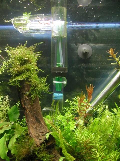 
|
|
|
This page was last updated 18 February 2002 | ||