| [E-mail] | |||
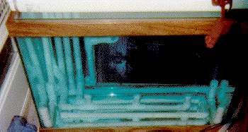
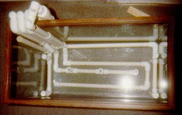
This is front-view picture of the tank in operation prior to adding any
substrate. The water is blue from a dye I added to check water flow patterns.
Vertical tubing in the tank consists of (from left to right):
The horizontal tubing that borders the outside walls of the tank (has towers sticking up at the corners is the diffusion system. The towers are the diffusers and direct water in a clockwise direction in this tank. If you look at the diffuser in the right back corner of the tank, you can just make out the two 1/4" holes drilled in it to direct water. The identical diffuser beside it is a reflection in the glass.
The tubing that lays across the bottom and has three small towers sticking up is the substrate skimmer tubing. The towers are the drains and each has four holes drilled in the cap on top.
The other horizontal tubing in the tank is the nutrient injection system.
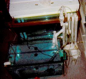
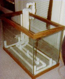
This is a picture of the test setup from behind. The tank closest to the
camera is the settling tank. Vertical tubing from right to left in the picture
consists of:
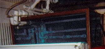
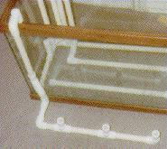
This is a picture of the tank from above. Note the holes drilled in the
substrate skimmer tubing caps to serve as drain grates.
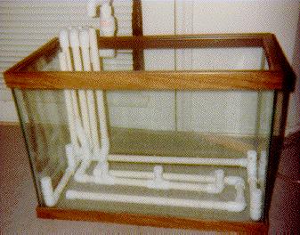
This is a picture of the tank prior to assembly. The tubing may be easier to
see than in the first picture.
This is a picture from above the tank prior to assembly. The camera flash
interfered with this picture some.
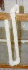
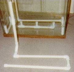
This is a picture of the tank, viewed at a diagonal angle prior to assembly.
The hook-shaped tubing above the tank is to prevent water from spilling onto
the carpet if the check valve leaks.
This is a picture of the diffuser system component outside the tank.
This is a picture of the surface skimmer outside the tank.
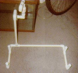
This is a picture of the substrate flow system (nutrient injection) outside the
tank.
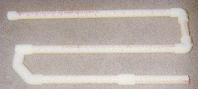
This is a picture of the underside of the substrate flow system. The tube
across the top of the picture has visible perforations along the centerline of
the tube. Perforations in the other tubes are too small for the scanner to
pick out.
This is a picture of the subsrate skimmer outside the tank.
![[Tank]](tank2t.jpg)
This is a photo of my 55g tank right after trimming, a few months prior to
teardown. The PVC tubing inside the tank was used for prototype implementations
of my surface skimmer and substrate skimmer designs. The two anubias nana in
the picture had been moved to the tank's location at the time of the picture
in-tank and had been in-place for over 3 years. The large dark object on the
left wall of the tank is an apple snail.
David W. Webb
Enterprise Computing Provisioning
Texas Instruments Inc. Dallas, TX USA
(214) 575-3443 (voice)  MSGID:       DAWB
(214) 575-4853 (fax)    Internet:    dwebb-at-ti.com
(214) 581-2380 (pager)  Text Pager:  pgr-at-ti.com Subj:PAGE:David Webb
From dwebb-at-ti.com Sat May 11 23:10:26 1996
Date: Tue, 19 Mar 1996 14:16:22 -0800
From: "David W. Webb" <dwebb-at-ti.com>
To: Erik Olson (e-mail)
Subject: Re: System design photos

    [The following text is in the "ISO-8859-1" character set]
    [Your display is set for the "US-ASCII" character set]
    [Some characters may be displayed incorrectly]


>  From: Erik Olson <(e-mail)>, on 3/19/96 11:04 AM:
>  Question: did you post an article explaining all this stuff?  I do have a
>  short description of your overflow skimmer part in the Tech section of
  the Krib, but I wonder if your overall article on the fertilization
>  system got lost somewhere.  If you can point me to a general date you
>  posted it, I have all my APDs archived & can pull it from there.

I posted a few articles about these designs over the last 10 months or so.  I
found as many of them as I could and included the references below.  I also
included the text from two other designs.  Note that I modified my
nutrient-injection system (substrate flow system) designs due to space
limitations in the 20g (and my 55g).

As far as I can tell, my first mention on the APD of the substrate flow system
is
here.

The explanation of my substrate flow design is
here.

Further discussion of my tank plans is at:
here.
(I wound up throwing the 50g away.)

I made another mention of my plans
here.
The 40g actually wound up being a 29g and a 20h.  I did a vermiculite-sand
substrate on the 20 with a 10g sump and used the 29 for a sump for my 55g.  The
laterite experiment will also have to wait until I get another 20g tank.

I talked briefly about my 20h implementation (the one pictured)
here.

I mention an advantage of settling tanks
here.
Charley Bay and I pretty much talked each other into switching to settling
tanks instead of trickle filters.

I talked about my 55g setup, pre-planting
here.

David Whittaker, the first person I know of who implemented my designs, wrote
an article on his "Webb-Kelley tank"
here
and
here.

Here are other articles that I have written for emailing to people:

------------------------------------------------
When I tear my tank down, I'm planning on a sub-gravel plumbing system
with diffusers that stick up a few inches above the gravel and create
a definite lower-level flow pattern.

I'm hoping that this flow will help my plants metabolize nutrients more
effectively by constantly delivering fresh nutrients.  I'm also hoping
that this flow pattern will keep the detrius off of the gravel and
plant leaves and help flush it down the trickle filter.

I have a 55 gallon.  I am planning to put one diffuser in each corner
and one in the back.  I will either attempt to create a counter-
clockwise flow pattern or a half and half flow pattern.  I think the
counter-clockwise pattern will take less pump, so that's what I'm
looking at right now.

I am also planning two or three center-drains at the gravel level.
Maybe I'll cover the drains with some coarse gravel so they aren't
visible.  I plan to cover the openings for these drains with coarse
mesh to keep from sucking down a fish.  These will be plumbed with a
straight siphon for periodic usage and with a loopback (smart) siphon
for continuous usage.  Hopefully, opening the ball valve on one of
these will suck down any debris that refuses to follow the current up
to the tank drain.

Under the gravel will also be a substrate aeration system.  It will
consist of 1/2" PVC tubing with 2 rows of holes, angled at 90 degrees
from one another.  The holes will be positioned at the bottom of
the tube.

I've mapped everything out like this.

|================================================================|
|DiiiiiiiiiiiiiiiiiiiiiiiiiiiiiiDiiiiiiiiiiiiiiiiiiiiiiiiiiiiiiiD|
|isGGGGGGGGGGGGGGGGGGGGGGGGGGGGGGGGGGGGGGGGGGGGGGGGGGGGGGGGGGGGGi|
|is                                                            Gi|
|isGGGGGGGGGGGGGGGGGGGGGGGGGGGGGGGGGGGGGGGGGGGGGGGGGGGGGGGGGGGGGi|
|isssssssssssssssssSssssssssssssSssssssssssssS                 Gi|
|i GGGGGGGGGGGGGGGGGGGGGGGGGGGGGGGGGGGGGGGGGGGGGGGGGGGGGGGGGGGGGi|
|i                                                             Gi|
|i GGGGGGGGGGGGGGGGGGGGGGGGGGGGGGGGGGGGGGGGGGGGGGGGGGGGGGGGGGGGGi|
|D                                                              D|
|================================================================|

D = Diffuser.  Each of these pokes its head about 2" out above the gravel.
    Slots in each head will direct the water flow.  The heads will screw in
    to allow for changes in head design and direction.  The tube from the
    pump is in the right-back corner of the tank.
i = Tubing leading to the diffusers.  Outside the tank, I will use a check-
    valve leading to a loop-back to the sump.  If the power shuts off, the
    check valve opens when the feedback siphon starts, and air enters the
    siphon.  When the power comes on, the check valve closes because of the
    water pressure from the pump.  Any water that gets past the check valve
    drains back to the sump.
S = Substrate drains.  Each of these will have its own tube and siphon.
s = Tubing for substrate drains.  Ball valves will allow flow control
    into the high loop-back or the low loop-back, depending on the desired
    siphon speed, or no siphoning at all.  The substrate drain tubing will
    exit in the left-back corner of the tank, along with the skimmer drain
    tubing (not shown).  Each substrate drain will have it's own tubing and
    control valve.
G = Substrate aeration system.  A small coupling in the diffuser tubing will
    allow a small amount of water to enter the substrate aeration system.
    The top of the substrate aeration system will be open to the air.

All control valves will be positioned outside the tank where they're easy
to get to.  Quick-release couplings will make disassembly, cleaning, and
part replacement easy.

I will probably have to modify the sizes on the diffusers to get an even
flow out of each.

I also plan to use smaller holes in the substrate aeration system towards
the end with the inlet tube.

--------------------------------------------------
"Automatic vacuum" tank drain.
Designed by David W. Webb
dwebb-at-ti.com

The automatic vacuum uses a loop-back siphon design to keep from draining the
tank when it is in automatic mode.  In high-speed mode, it will quickly drain
the tank.

I designed this drain after getting annoyed with having to vacuum the surface
of my gravel more often than I thought should be necessary.  This tank drain
is intended for non-drilled tanks and tanks that can't be drilled safely.

This system relies on water motion within the tank to move debris to the
vacuum.  A water-flow swirl in the tank will provide this motion.  Note:
This system is designed with plant tanks in mind.  Extra aeration procedures
may be necessary in a normal tank with a swirl water flow.

Blanket Disclaimer:
I am not responsible for any damage to personal property or injury to persons
if you use any of my suggestions or designs.  I reserve the right to modify
my designs at any time.

     __                   C.-----------------D.
    //\\                   |  -------------  |
   || =\\==================| |===    G.| | | |
   || #                    | |  #  ----  | | |
   || #~~~~~~~~~~~~~~~~~~~~| |~~# |  -- ~| | |
   || #                    | |  # | |F.| | | |
   || #                    | |  # | |  | | | |
   || #                    | |  # | |  | | | |
   || #                    | |  # | |  | | | |E.
   || #                    | |  # | |  | | | |
   || #          A.        | |  # | |  | | | |
   || #-at--at--at--at--at--at--at--at--at--at-###-at--at--at--at--at--at--at-| |-at--at-# | |  | | | |
   || #          |  -------  |  # | |J.| | | |
   || #        B. -----------   # |  ==   -  |
   || ########################### |  ==------
   ||                             | |
    \\________             I.     | |
     \________\         ---==-----  |
              \\     H.|  -==-------
            ===||======| |=====
            #  ||  |          #
            #  ||  |          #
            #  ||  |          #
            # _||_ |----------#
            #~|  |~|~~~~~~~~~~#
            # |  | |          #
            ###################

A.  The gravel vacuum drain.  This should be covered with a screen of some
    sort to keep fish and gravel out.  The screen should be removable and
    cleanable.  You want it fine enough to keep fish out, but coarse enough
    to pull in debris.  The drain should be as close to flush with the
    substrate surface as is possible.  It might be possible to lightly cover
    the drain and surrounding area with coarse gravel to make it less
    visible.  I plan to use three drains arranged linearly across the bottom
    of my 55 gallon tank.  I currently have one, and it isn't enough.  Each
    drain will have its own parts A. B. C. and D. and will have its own
    shut-off valve before they join at E.

B.  The J-tube should be as low as possible in your tank.  A good place to
    put it is under the gravel.
    The J-tube must be below the bottom of the waterfall (F.)  The waterfall
    will control the final resting water level of the tank when the pump is
    off.

C.  The siphon draws water out of the tank and into the velocity loop (E.)

D.  An air fitting on the outside elbow of the siphon provides an easy way to
    start the siphon.
    Joseph S. Sellinger suggests that you connect this fitting to the air
    venturii on one of your power heads.  I believe that this will work
    on higher flow power heads.  Beware that for this application, the power
    head needs to be in the tank and not in the sump, otherwise a siphon
    in the air tubing could slowly drain the tank.

E.  The velocity loop should drop as far down as is the tank is deep.  The
    velocity loop holds the water necessary to start or re-start the siphon.

F.  The waterfall drains the siphoned water into the sump.  The waterfall in
    this application controls the resting water level of the tank when the
    pump is off.

G.  The surge tube allows you to fill the velocity loop to start the siphon.
    It also acts to buffer water surges.  The top of the surge tube should be
    even with or above the top of the tank to prevent spilling any water
    during a surge.  (Surges may occur when you add water to the tank
    rapidly.)  You can reduce noise at this location by placing a drilled cap
    loosely over the top of the surge tube.  The drilled hole will prevent a
    siphon from forming and draining your tank, and the cap will muffle the
    sound of the water draining down the waterfall.

H.  The drain into the sump.  You may want to use a piece of filter material
    suspended under this drain or use a settling tank to catch debris.

I.  An individual shut-off valve for each     drain.

J.  The high-speed portion of the loop.  A shut-off valve positioned here
    controls whether this is on or not.  If you leave this side of the loop
    on for long, you will drain your tank.  Good for flushing out the vacuum
    system.

I recommend placing quick-disconnects at strategic places in this system so
you can easily tear it down for maintenance, modification, or repair.


David W. Webb
Enterprise Computing Provisioning
Texas Instruments Inc. Dallas, TX USA
(214) 575-3443 (voice)  MSGID:       DAWB
(214) 575-4853 (fax)    Internet:    dwebb-at-ti.com
(214) 581-2380 (pager)  Text Pager:  pgr-at-ti.com Subj:PAGE:David Webb
|
|
This page was last updated 29 October 1998 | ||